


Project Brief
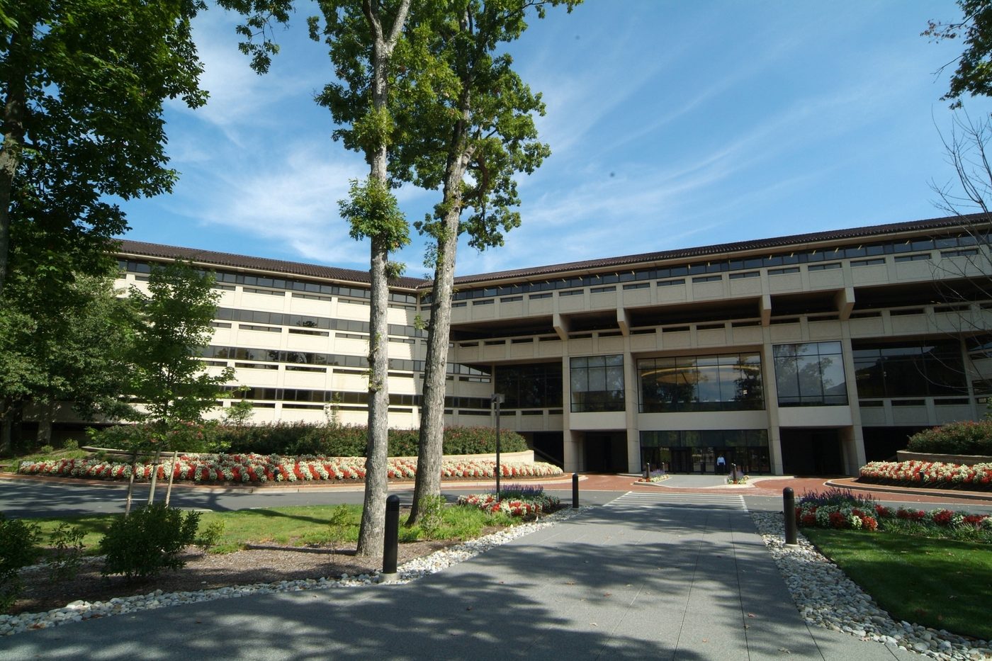
Verizon's campus at 1 Verizon Way in Basking Ridge runs its HVAC on pneumatic controls, which means the dampers, valves, and thermostats across the buildings all take their orders from compressed air. That air comes from one plant room, MER-105. If the air stops, the campus loses control of its heating and cooling. KeRi was the prime consultant for replacing that plant.
The design puts in three oil-lubricated variable speed rotary screw compressors, each rated 225 SCFM at 125 psi on a 50 HP motor, giving 675 SCFM of capacity across the set. Behind them sit two heated blower-purge desiccant dryers, duty and standby, drying the control air to a minus 40 degree pressure dew point on activated alumina, and a 240 gallon ASME Section VIII receiver with an automatic drain and an inspection port. The compressors carry low sound enclosures, heavy-duty intake filters, and automatic restart after a power failure. Each machine and dryer got a controller with a BACnet card, networked so the three stage as one plant and report back to the campus building management system, which KeRi coordinated with Verizon's own BMS vendor.
Around the equipment, the work stayed deliberately light on the building. New 6 inch concrete pads and neoprene isolation under each compressor, new filters and solenoid isolation valves, condensate to the floor drain, and new piping tied back into the existing distribution. On the electrical side KeRi reused and extended the existing feeders and the existing 100 amp and 20 amp breakers rather than pulling new circuits through a live plant room, adding a single new fused disconnect and keeping clear working space in front of the two 600 amp motor control centres already there.
The governing constraint is written on the drawings. All work is phased so that at any given moment only one compressor system is down or in demolition. The other two stay connected to building controls and stay running, one on duty and one as backup, and the building's compressed air system is never shut down during demolition or new work. KeRi issued the 90 percent set in May 2021, the 100 percent set a week later, and the bid set in June.
MEP Engineering Scope
What We Engineered
Mechanical and electrical design for the control air plant:
- Three 225 SCFM variable speed rotary screw compressors at 125 psi
- Two twin-tower desiccant dryers drying to a minus 40 degree dew point
- A 240 gallon ASME receiver, filtration, and isolation valves
- Concrete pads, vibration isolation, and new compressed air piping
- Existing feeders and breakers reused, with one new fused disconnect
- BACnet controls integrated to the campus BMS, phased so the air never stops
Systems by Discipline
01Compressed Air Plant
- Three oil-lubricated variable speed rotary screw compressors, each 225 SCFM at 125 psi on a 50 HP motor, with low sound enclosures and heavy-duty intake filtration
- High-efficiency motors with automatic restart after a power failure, so the plant comes back on its own
- Two heated blower-purge desiccant dryers at 390 SCFM, duty and standby, drying the control air to a minus 40 degree pressure dew point on activated alumina
- A 240 gallon ASME Section VIII receiver with automatic drain, relief valve, and an inspection port, epoxy coated inside and out
- New inlet and outlet filtration, solenoid isolation valves, and condensate run to the floor drain
02Installation & Piping
- New 6 inch concrete housekeeping pads under the compressors and the dryer set
- Two inch neoprene isolation pads at all four corners of every compressor
- New compressed air piping tied back into the existing distribution, with a piping schematic covering the whole plant
- Equipment laid out to keep manufacturer service clearances and a 3 foot clear working space in front of the electrical panels
- Existing control panel board and the existing mechanical system tanks left in place and worked around
03Electrical
- Existing feeders reused and extended to the new equipment rather than pulling new ones across a live plant room
- Existing 100A 480V three pole breakers reused for the three compressors and existing 20A breakers for the two dryers
- One new 100A 480V fused disconnect switch furnished for the new compressor
- Work coordinated around the two existing 600A motor control centers already in the room
- Circuits made safe and completed to the National Electrical Code, with panel directories updated
04Controls & Phasing
- Every compressor and dryer given a controller with a BACnet MS/TP card and networked together, so the three machines stage as one plant
- Integration coordinated with the owner's existing BMS vendor, who provided the controllers, wiring, and programming back to the campus system
- Solenoid isolation valves interlocked with dryer operation through the BMS
- Phasing written into the drawings: only one compressor system may be down or in demolition at any time, with the other two connected to building controls and running throughout
- No shutdown of the building's compressed air system permitted during demolition or new work
- Factory start-up, operation training, and extended parts and labour warranties specified at turnover
The Challenge
A corporate campus running pneumatic HVAC controls depends on one compressed air plant. Lose the air and the buildings lose control of their heating and cooling, so the plant that had to be replaced was also the plant that could not be switched off. The room was tight, live, and shared with two 600 amp motor control centres, and the existing control panel board and mechanical system tanks had to stay exactly where they were.
Our Solution
KeRi designed the replacement as three variable speed compressors backed by duty and standby desiccant dryers and a 240 gallon receiver, networked over BACnet so they stage as one plant and report to the campus building management system. The installation was kept light on the building, reusing and extending the existing feeders and breakers instead of pulling new circuits, and the whole job was phased on the drawings so that only one compressor system is ever down at a time while the other two keep the campus controls supplied.
Previous Project zColo Chicago Suite 142 Next Project Verizon Switchgear Cooling